Tuesday, August 31, 2010

Law of Thermodynamics

The 1st Law of Thermodynamics tells us that energy is neither created nor destroyed, thus the energy of the universe is a constant. However, energy can certainly be transferred from one part of the universe to another. To work out thermodynamic problems we will need to isolate a certain portion of the universe, the system, from the remainder of the universe, the surroundings.
The energy transfer between different systems can be expressed as:
E1 = E2         (1)
where
E1 = initial energy
E2 = final energy
The internal energy encompasses:
  • The kinetic energy associated with the motions of the atoms
  • The potential energy stored in the chemical bonds of the molecules
  • The gravitational energy of the system

Monday, August 30, 2010

Band Pass Filter with LC

LC Band pass filters are usually LC filters containing resonator combinations of inductance and capacitance which are designed mathematically to respond to design frequencies while rejecting all other out of band frequencies. Because LC bandpass filters have inherent limitations these statements should not be taken too literally.
Now we move from the simple to the complicated. By this stage you should be able to understand:
unloaded Q ( QU )
loaded Q ( QL )
reactance.
LC circuit combination for any given frequency.
LC Band pass filters are derived from tables named after the mathematicians who did the original calculations.
The main filters considered are:
Butterworth
Chebyschev
Bessel
Gaussian

Friday, August 27, 2010

Harmonic Trap of Filter

With the addition of one small component, a capacitor, we can transform a low pass filter into a filter with near infinite attenuation at a designed trap frequency. I call this an "harmonic trap filter".
Let's look at the old low pass filter in figure 1 below.

                                                             schematic of low pass filter


I presume you have already completed the tutorial on low pass filter and understand them fully. Now to construct an harmonic trap filter all I need to do is insert a capacitor C3 as in figure 2 below.

                                                           harmonic trap filter schematic

Thursday, August 26, 2010

Filter of Narrow Band

WHAT ARE NARROW BAND FILTERS?

Narrow band filters are filters where the fractional bandwidth is extremely small in a relative sense. My personal definition of a narrow band filter is where the narrow band filter has a fractional bandwidth NOT exceeding 1%. These filters can be adapted to become fixed or tunable antenna pre-selector filters.
A filter with a bandwidth of 200 Khz ( ± 100 Khz ) centred around 7100 Khz would represent a bandwidth of about 2.86%
As just one example of a narrow band filter for the front end of a receiver I'll look at a double tuned front end filter for a single frequency receiver built to receive WWV or VNG time signals at 5000 Khz. These are amplitude moduated ( AM ) signals with modulation not exceeding 1000 Hz. Strictly speaking all we want to receive is around 4999 Khz to 5001 Khz, that is only a 2 Khz bandwidth. Technically it is quite feasible to construct a crystal filter to do this job but that is not the subject of our discussion here.

Wednesday, August 25, 2010

Low Pass Filter

What are low pass filters?

We will start with low pass filters ( LPF ) because they are the basis of other filter designs. High pass or band pass filters are often simply transformations from low pass filter designs.
Perhaps the simplest low pass filter is the classic butterworth pi network design where the reactive elements are of a constant impedance e.g. 50 ohms and the design Q = 1.
 Figure 1 - butterworth pi network low pass filter diagram

This example is most frequently used in the output of a transmitter to minimise harmonic output and eliminate QRM. As with all simple designs there is a limit to the benefit to be gained. If such a filter were designed with a cut off (Fc) of 7.5 Mhz the attenuation only becomes significant well away from that frequency.

Low pass filter is two L networks

It is simply two L networks added together like this to form a low pass pi network filter:

 Figure 2 - two L network low pass filters
 

Tuesday, August 24, 2010

High Pass Filter

What are high pass filters?

Assuming you have mastered the design of low pass LC filters we will now proceed to the design of a high pass filters. A high pass filter is simply the transformation of a low pass filter. For our purposes, we will say we need a five pole butterworth filter with a cut off frequency Fc at 2000 Khz. That is we want to pass all frequencies above 2000 Khz (2 Mhz) but attenuate those below 2000 Khz.
Perhaps this might be required for the antenna input to a receiver where AM Radio interference is proving troublesome.

Design Procedure for high pass filters

If you have done the tutorial on low pass filters and are confused by what comes next, be aware there are literally hundreds of low pass filter types. However all low pass filters transform to high pass filters.
Let us first review the design procedure for a similar five pole filter but as a low pass filter. From our design tables we know that for equal source and loads:

Monday, August 23, 2010

Formulas of Electrical

Common electrical units used in formulas and equations are:
  • Volt- unit of electrical potential or motive force - potential is required to send one ampere of current through one ohm of resistance
  • Ohm - unit of resistance - one ohm is the resistance offered to the passage of one ampere when impelled by one volt
  • Ampere - units of current - one ampere is the current which one volt can send through a resistance of one ohm
  • Watt - unit of electrical energy or power - one watt is the product of one ampere and one volt - one ampere of current flowing under the force of one volt gives one watt of energy
  • Volt Ampere - product of volts and amperes as shown by a voltmeter and ammeter - in direct current systems the volt ampere is the same as watts or the energy delivered - in alternating current systems - the volts and amperes may or may not be 100% synchronous - when synchronous the volt amperes equals the watts on a wattmeter - when not synchronous volt amperes exceed watts - reactive power
  • Kilovolt Ampere - one kilovolt ampere - KVA - is equal to 1,000 volt amperes
  • Power Factor- ratio of watts to volt amperes

Friday, August 20, 2010

Parallel and Series Control Valve

Control Valves in Parallel

The resulting Kv or Cv if two valves are installed in parallel can be calculated as
Kvt = Kv1 + Kv2          (1)
where
Kvt = resulting Kv
Kv1 = Kv valve 1
Kv2 = Kv valve 2

Control Valves in Series


The resulting Kv or Cv if two valves are installed in series can be calculated as
1 / (Kvt)2 =  1 / (Kv1)2 + 1 / (Kv2)2           (2)

Thursday, August 19, 2010

Flow Factor (Kv) and Flow Coefficient (Cv)

The flow coefficient - Cv - and the flow factor - Kv - are commonly used to specify the capacity of control valves.

Flow Coefficient - Cv

It is often convenient to express the capacities and flow characteristics of control valves in terms of the
  • Flow Coefficient - Cv
The flow coefficient - Cv - is based on the imperial units system and is defined as:
  • the flow of water through a valve at 60 oF in US gallon/minute at a pressure drop of 1 lb/in2
The flow coefficient is commonly used in the U.S.

Flow Factor - Kv

The metric equivalent of the flow coefficient - Cv - is based on the SI-system and is called the
  • Flow Factor - Kv
The flow factor - Kv - is defined as
  • the flow of water with temperature ranging 5 - 30 oC through a valve in cubic meters per hour (m3/h) with a pressure drop of 1 bar
The flow factor is commonly used outside U.S.

Converting between Flow Coefficient Cv and Flow Factor Kv

The relationship between Cv and Kv can be expressed as:
  • Cv = 1.16 Kv         (1)
  • Kv = 0.853 Cv         (2)

Wednesday, August 18, 2010

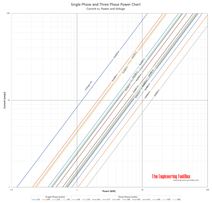
Converting Between Single Phase and 3 Phase in Ampere

Converting amperage between single phase (120, 240 and 480 Voltage) and three phase (240 and 480 Voltage)

Sometimes it is necessary to turn between power (VA), voltage (V) and amperage (A). The diagram and table below can be used to convert amperage between single phase and three phase equipment and vice versa.


power va volt ampere diagram


Monday, August 16, 2010

Conductivity, Resistivity and Temperature Coefficients for some Common Materials

The factor in the resistance which takes into account the nature of the material is the resistivity.

Material Resistivity Coefficient      - ρ -
(ohm m)
Temperature Coefficient per degree C          Conductivity             - σ -
(1 /Ωm)
Aluminum 2.65 x 10⁻⁸ 3.8 x 10⁻³ 3.77 x 10⁷
Antimony 41.8 x 10⁻⁸    
Beryllium 4.0 x 10⁻⁸    
Bismuth 115 x 10-8    
Cadmium 7.4 x 10⁻⁸    
Carbon (graphite)1) 3 - 60 x 10-5 -4.8 x 10⁻³
Chromel (alloy of chromium and aluminum) 0.58 x 10⁻³
Chromium 13 x 10-8    
Cobalt 9 x 10⁻⁸    
Constantan 49 x 10-8 0 0.20 x 10⁷
Copper 1.724 x 10⁻⁸ 4.29 x 10⁻³ 5.95 x 10⁷
Eureka   0.1 x 10⁻³  
Iron 9.71 x 10⁻⁸ 6.41 x 10⁻³ 1.03 x 10⁷
Germanium1) 1 - 500 x 10-3 -50 x 10-3
Glass 1 - 10000 x 109
Gold 2.24 x 10⁻⁸
Iridium 5.3 x 10⁻⁸    
Iron 9.7 x 10⁻⁸    
Lead 20.6 x 10⁻⁸ 0.45 x 10⁷
Magnesium 4.45 x 10⁻⁸    
Manganese 185 x 10-8    
Mercury 98.4 x 10⁻⁸ 8.9 x 10⁻³ 0.10 x 10⁷
Molybdenum 5.2 x 10⁻⁸    
Nickel 6.85 x 10⁻⁸ 6.41 x 10⁻³
Nichrome (alloy of nickel and chromium) 0.40 x 10⁻³
Niobium (Columbium) 13 x 10-8    
Osmium 9 x 10⁻⁸    
Platinum 10.5 x 10⁻⁸ 3.93 x 10⁻³ 0.943 x 10⁷
Plutonium 141.4 x 10⁻⁸    
Potassium 7.01 x 10⁻⁸    
Quartz
(fused)
7.5 x 10¹⁷
Rhodium 4.6 x 10⁻⁸    
Rubber - hard 1 - 100 x 1013
Selenium 12.0 x 10⁻⁸    
Silicon1) 0.1-60 -70 x 10-3
Silver 1.59 x 10⁻⁸ 6.1 x 10⁻³ 6.29 x 10⁷
Sodium 4.2 x 10⁻⁸    
Tantalum 12.4 x 10⁻⁸    
Thorium 18 x 10-8    
Tin 11.0 x 10⁻⁸    
Titanium 43 x 10-8    
Tungsten 5.65 x 10⁻⁸ 4.5 x 10⁻³ 1.79 x 10⁷
Uranium 30 x 10-8    
Vanadium 25 x 10-8    
Zinc 5.92 x 10⁻⁸    
1) The resistivity depends strongly on the presence of impurities in the material
2) Resistivity and Temperature Coefficients at 20oC reference

Friday, August 13, 2010

Variable-Frequency Drives (Heat Loss and Required Ventilation)

Variable-frequency drives are common for controlling speed of electric motors in applications with fans, pumps, compressors, elevators, extruders etc.

Heat Loss from a Variable-Frequency Drive

A certain amount of the power transferred through the variable-frequency drive to the motor is lost as heat to the surroundings. The heat loss from a drive can be expressed as
Hloss = Pt (1 - ηd)         (1)
where
Hloss = heat loss to the variable frequency drive surroundings (W)
Pt = electrical power through the variable frequency drive (W)
ηd = variable frequency drive efficiency
The heat loss can alternatively be expressed in imperial units
Hloss = Pt 3,412 (1 - ηd)         (1b)
where
Hloss = heat loss to the variable frequency drive surroundings (btu/h)
Pt = power in to the frequency drive (W)
ηd = variable frequency drive efficiency

Wednesday, August 11, 2010

Binary Versus Decimal Numeration

Let's count from zero to twenty using four different kinds of numeration systems: hash marks, Roman numerals, decimal, and binary:

System:    Hash Marks               Roman     Decimal     Binary
-------    ----------               -----     -------     ------
Zero       n/a                       n/a         0          0 
One        |                          I          1          1 
Two        ||                         II         2          10
Three      |||                        III        3          11
Four       ||||                       IV         4          100
Five       /|||/                      V          5          101
Six        /|||/ |                    VI         6          110
Seven      /|||/ ||                   VII        7          111
Eight      /|||/ |||                  VIII       8          1000
Nine       /|||/ ||||                 IX         9          1001
Ten        /|||/ /|||/                X          10         1010
Eleven     /|||/ /|||/ |              XI         11         1011
Twelve     /|||/ /|||/ ||             XII        12         1100
Thirteen   /|||/ /|||/ |||            XIII       13         1101
Fourteen   /|||/ /|||/ ||||           XIV        14         1110
Fifteen    /|||/ /|||/ /|||/          XV         15         1111
Sixteen    /|||/ /|||/ /|||/ |        XVI        16         10000
Seventeen  /|||/ /|||/ /|||/ ||       XVII       17         10001
Eighteen   /|||/ /|||/ /|||/ |||      XVIII      18         10010
Nineteen   /|||/ /|||/ /|||/ ||||     XIX        19         10011
Twenty     /|||/ /|||/ /|||/ /|||/    XX         20         10100

Tuesday, August 10, 2010

Starting Device for Electrical Motor

Common starting methods available for squirrel cage motors are
  • direct-on-line starters
  • star-delta starters
  • frequency drives
  • soft starters

Direct-on-Line Starters

The simplest and most common starting device is the direct-on-line starter where the equipment consists of a main contactor and a thermal or electronic overload relay.
The disadvantage of the direct-on-line method is very high starting current (6 to 10 times the rated motor currents) and high starting torque, causing
  • slipping belts, heavy wear on bearings and gear boxes
  • damaged products in the process
  • water hammers in piping systems

Monday, August 9, 2010

Power Factor for Electrical Motor

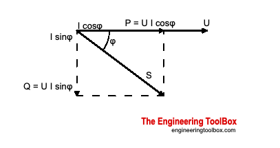
The power factor of an AC electric power system is defined as the ratio of the active (true or real) power to the apparent power
where
  • Active (Real or True) Power is measured in watts (W) and is the power drawn by the electrical resistance of a system doing useful work.
  • Apparent Power is measured in volt-amperes (VA) and is the voltage on an AC system multiplied by all the current that flows in it. It is the vector sum of the active and the reactive power.
  • Reactive Power  is measured in volt-amperes reactive (VAR). Reactive Power is power stored in and discharged by inductive motors, transformers and solenoids
Reactive power is required for the magnetization of a motor but doesn't perform any action. The reactive power required by inductive loads increases the amounts of apparent power - measured in kilovolt amps (kVA) - in the distribution system. Increasing of the reactive and apparent power will cause the power factor - PF - to decrease.

Power Factor

It is common to define the Power Factor - PF - as the cosine of the phase angle between voltage and current - or the "cosφ".
power factor active true reactive apparent power

Heat Loss in Electrical Motor

Heat loss from electric motors during operation can be indicated to
Size of Motor
(kW)
Heat Loss
(Watts/kW)
0 - 2 250
3 - 15 150
15 - 150 100
150 - 80
  • 1 kW = 1.34 hp
  • 1 hp = 0.746 k W

Alternative - with Imperial Units 

Nameplate Rating Motor Efficiency
Average
Heat Loss to Room Air (Btu per Hr per Rated Hp)
(Hp) Motor in Room
Driven Device inside Room
Motor in Room
Driven Devise Outside Room
Motor Outside Room
Driven Device inside Room
1/8 to 1/2 0.60 4250 1700 2550
1/2 to 3 0.69 3650 1100 2550
3 to 20 0.85 2950 400 2550
  • 1 Btu/h = 0.293 W

Friday, August 6, 2010

Types of NEMA Electrical Enclosure

General information on the definitions of NEMA enclosure types:
For enclosures used in

Non-Hazardous Locations

Type 1 : General Purpose - Indoor

  • Enclosures constructed for indoor use to provide a degree of protection to personnel against incidental contact with the enclosed equipment and to provide a degree of protection against falling dirt.

Type 2 : Drip-Proof - Indoor

  • Enclosures constructed for indoor use to provide a degree of protection to personnel against incidental contact with the enclosed equipment, to provide a degree of protection against falling dirt, and to provide a degree of protection against dripping and light splashing of liquids.

Design of Nema A, B, C and D for Electric Motor Control

Different motors of the same nominal horsepower can have varying starting current, torque curves, speeds, and other variables. Selection of a particular motor for an intended task must take all engineering parameters into account.
The four NEMA (National Electrical Manufacturers Association) designs have unique speed-torque-slip relationships making them suitable to different type of applications:

NEMA design A

  • maximum 5% slip
  • high to medium starting current
  • normal lock rotor torque
  • normal breakdown torque
  • suited for a broad variety of applications - as fans and pumps


Thursday, August 5, 2010

Efficiency of Electrical Motor

Electrical motor efficiency is the ratio between the shaft output power - and the electrical input power.

Electrical Motor Efficiency when Shaft Output is measured in Watt

If power output is measured in Watt (W), efficiency an be expressed as:
ηm = Pout / Pin?             (1)
where
ηm = motor efficiency
Pout = shaft power out (Watt, W)
Pin = electric power in to the motor (Watt, W)

Electrical Motor Efficiency when Shaft Output is measured in Horsepower

If power output is measured in horsepower (hp), efficiency can be expressed as:
ηm = Pout 746 / Pin            (2)
where
Pout = shaft power out (horsepower, hp)
Pin = electric power in to the motor (Watt, W)

Wednesday, August 4, 2010

Stability Analysis Using Nyquist Plot

There are a number of polar graph options for studying control systems including the nyquist, inverse polar plot and the nichols plot.  The nyquist open loop polar plot indicates the degree of stability, and the adjustments required and provides stability information for systems containing time delays.  Polar plots are not used exclusively because,without powerful computing facilities, they can be difficult to generate at a detailed level and they do not directly yield frequency values.

The Nyquist plot is obtained by simply plotting a locus of imaginary(G(j ω)) versus Real(G(j ω)) at the full range of frequencies from ( - ¥ to + ¥ ) It is very easy to produce nyquist plots by hand or by using proprietary software packages such as Matlab.   Links below show how bode and nyquist plots can be produced using Excel and using Mathcad.  The plots below have been produced in minutes using Mathcad..


The nyquist plot fundamentals are shown below....

Velocity Feedback control

Tuesday, August 3, 2010

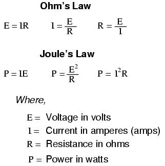
Basic Circuit Equations and Laws

Ohm's and Joule's Laws


Monday, August 2, 2010

Diode

Diodes are semiconductor devices which might be described as passing current in one direction only. The latter part of that statement applies equally to vacuum tube diodes. Diodes however are far more versatile devices than that. They are extremely versatile in fact. It might pay you to review the topic of atom and electron theory.
Diodes can be used as voltage regulators, tuning devices in rf tuned circuits, frequency multiplying devices in rf circuits, mixing devices in rf circuits, switching applications or can be used to make logic decisions in digital circuits. There are also diodes which emit "light", of course these are known as light-emitting-diodes or LED's. As we say diodes are extremely versatile.