Example 1) Temperature measurement before a chemical reactor:
The feed temperature, T3, to an isothermal chemical reactor should be controlled very accurately in the range of 400K. The product quality is measured only once every shift by laboratory analysis. The operator adjusts the set point of the feed temperature controller to achieve the desired product quality. What temperature sensor do you recommend?
The feed temperature, T3, to an isothermal chemical reactor should be controlled very accurately in the range of 400K. The product quality is measured only once every shift by laboratory analysis. The operator adjusts the set point of the feed temperature controller to achieve the desired product quality. What temperature sensor do you recommend?
Solution:
Here, high accuracy is required in the range of 400K. Since accuracy is required, a thermocouple is not recommended. Since the temperature range is outside the region for a thermistor, an RTD sensor is recommended.
Here, high accuracy is required in the range of 400K. Since accuracy is required, a thermocouple is not recommended. Since the temperature range is outside the region for a thermistor, an RTD sensor is recommended.
Example 2) Distillation tray temperature control:
You have decided to use a tray temperature measurement in place of an analyzer for distillate composition control. This approach is referred to as inferential control (see Marlin, 2000, Chapter 17) and is used often to achieve reasonable control with low cost equipment. You would like to provide another measurement on the same tray to validate the sensor used for control. How would you do this?
You have decided to use a tray temperature measurement in place of an analyzer for distillate composition control. This approach is referred to as inferential control (see Marlin, 2000, Chapter 17) and is used often to achieve reasonable control with low cost equipment. You would like to provide another measurement on the same tray to validate the sensor used for control. How would you do this?

Solution:
Recall that the temperature sensor is protected from the process environment by a thermowell. Since we generally try to reduce the number of “holes” in a pressure vessel, we will place a second thermocouple in the same thermowell. This will provide a check on the temperature for most possible faults, such as a wire break. Clearly, both sensors will respond in the same manner to a fault like a buildup of material on the thermowell that slows the response of the sensors. This type of fault is not very likely in a distillation tower. This fault could occur in a chemical reactor, where coke can build up over time.
Recall that the temperature sensor is protected from the process environment by a thermowell. Since we generally try to reduce the number of “holes” in a pressure vessel, we will place a second thermocouple in the same thermowell. This will provide a check on the temperature for most possible faults, such as a wire break. Clearly, both sensors will respond in the same manner to a fault like a buildup of material on the thermowell that slows the response of the sensors. This type of fault is not very likely in a distillation tower. This fault could occur in a chemical reactor, where coke can build up over time.
Example 3) Temperature measurement in a packed bed reactor:
A highly exothermic chemical reaction is taking place in an adiabatic, catalytic packed bed reactor. Where would you place the temperature sensor to ensure that the maximum temperature is not exceeded?
A highly exothermic chemical reaction is taking place in an adiabatic, catalytic packed bed reactor. Where would you place the temperature sensor to ensure that the maximum temperature is not exceeded?
Solution:
This would be a simple problem if the flow through the reactor were plug flow; then, a single sensor at the outlet would provide sufficient information. However, the flow is not likely to closely approximate ideal, plug flow, so sensors should be placed throughout the bed. The details vary with the reactor size, catalyst activity and thermal properties, but typically, these reactors have many thermowells, each with several thermocouples measuring temperatures at different points down the length of the reactor. An important feature of the feedback control system would be to monitor all temperatures and control the highest to a set point.
This would be a simple problem if the flow through the reactor were plug flow; then, a single sensor at the outlet would provide sufficient information. However, the flow is not likely to closely approximate ideal, plug flow, so sensors should be placed throughout the bed. The details vary with the reactor size, catalyst activity and thermal properties, but typically, these reactors have many thermowells, each with several thermocouples measuring temperatures at different points down the length of the reactor. An important feature of the feedback control system would be to monitor all temperatures and control the highest to a set point.
Example 4) Temperature measurement:
You would like to measure a temperature in a flash separator, T6. Great accuracy is not desired, because we plan to install an onstream analyzer. The stream pressure is 10 MPa, and the temperature range is 273-373 K. What sensor would you select?
You would like to measure a temperature in a flash separator, T6. Great accuracy is not desired, because we plan to install an onstream analyzer. The stream pressure is 10 MPa, and the temperature range is 273-373 K. What sensor would you select?
Solution:
Since high accuracy is not required, a thermocouple is recommended. The pressure has no influence on the selection, and the thermocouple recommended in Table 1 is Type J for this temperature range.
Since high accuracy is not required, a thermocouple is recommended. The pressure has no influence on the selection, and the thermocouple recommended in Table 1 is Type J for this temperature range.
Example 5) Flow measurement for gas with changing composition:
You want to measure the flow rate of a hydrocarbon stream. Great accuracy is not required; the accuracy typically achieved with an orifice meter (±3-5%) is acceptable. Because of changes to upstream operation, the composition of the stream can change within the limits shown in the data below; however the pressure does not vary significantly. What sensor do you recommend?
You want to measure the flow rate of a hydrocarbon stream. Great accuracy is not required; the accuracy typically achieved with an orifice meter (±3-5%) is acceptable. Because of changes to upstream operation, the composition of the stream can change within the limits shown in the data below; however the pressure does not vary significantly. What sensor do you recommend?
 |
|
Solution:
The standard orifice meter measures only DP = P1- P3 and assumes the coefficient of resistance and the density are constant, i.e., Fsensor = Kv (DP/r0)0.5 , with r0 the density at the design or base case. The error due to the assumption can be evaluated by comparing the square root of the densities at the design point and the maximum deviation in molecular weight.
The standard orifice meter measures only DP = P1- P3 and assumes the coefficient of resistance and the density are constant, i.e., Fsensor = Kv (DP/r0)0.5 , with r0 the density at the design or base case. The error due to the assumption can be evaluated by comparing the square root of the densities at the design point and the maximum deviation in molecular weight.
The error due to the change in density will be a bias of -8 percent, which would be in addition to other inaccuracies associated with an orifice meter. The actual volumetric flow rate would be less than recorded by a sensor assuming constant density. If the flow meter were the basis for purchasing the stream, you would be paying 8 percent too much! Where accuracy is needed, compensation should be applied by measuring the molecular weight of the gas and correcting as shown in the equation above.
Example 6) Effect of pressure on a gas flow sensor:
You wish to measure the vapor product from a distillation column. You have ascertained that an orifice sensor is a good choice. Decide the proper location for the sensor, F1 or F2.
You wish to measure the vapor product from a distillation column. You have ascertained that an orifice sensor is a good choice. Decide the proper location for the sensor, F1 or F2.
Solution:
The two likely choices for measuring the gas stream are 1) immediately after the drum before the pressure control valve and 2) after the control valve. The key factor is accuracy; which location more closely satisfies the assumptions associated with the standard orifice sensor? Since the standard orifice sensor assumes constant density, you should select the location that has the most constant pressure. The pressure in the overhead circuit is controlled, while the pressure downstream from the valve will vary with the flow rate. Therefore, the sensor before the control valve, F1, is chosen.
The two likely choices for measuring the gas stream are 1) immediately after the drum before the pressure control valve and 2) after the control valve. The key factor is accuracy; which location more closely satisfies the assumptions associated with the standard orifice sensor? Since the standard orifice sensor assumes constant density, you should select the location that has the most constant pressure. The pressure in the overhead circuit is controlled, while the pressure downstream from the valve will vary with the flow rate. Therefore, the sensor before the control valve, F1, is chosen.
Example 7) Pressure drop in measuring gas flows:
The flow of gas through a compressor is a very important variable. It is one important factor for the amount of energy required. In addition, a minimum flow rate is required to prevent unstable flow and mechanical damage to the compressor. What sensor would you recommend to measure flow at the suction to a compressor?
The flow of gas through a compressor is a very important variable. It is one important factor for the amount of energy required. In addition, a minimum flow rate is required to prevent unstable flow and mechanical damage to the compressor. What sensor would you recommend to measure flow at the suction to a compressor?
Solution:
The work required by the compressor depends on several factors, including pressure rise. To achieve the desired (low) pressure in the process upstream of the compressor, the suction pressure must be lower to account for the non-recoverable pressure loss due to the flow sensor. Thus, the pressure loss requires additional work to achieve the desired inlet and outlet pressures. For this reason, a sensor with a very small pressure drop is selected. Usually, this would be an annubar or pitot tube.
The work required by the compressor depends on several factors, including pressure rise. To achieve the desired (low) pressure in the process upstream of the compressor, the suction pressure must be lower to account for the non-recoverable pressure loss due to the flow sensor. Thus, the pressure loss requires additional work to achieve the desired inlet and outlet pressures. For this reason, a sensor with a very small pressure drop is selected. Usually, this would be an annubar or pitot tube.
Example 8) Measuring a highly variable flow rate:
We want to measure the vapor flow rate, F4. The vapor flow rate from a flash drum varies over a large range because of changes in the upstream operation. The variation in total flow rate is about 20-100% of its maximum during normal operation; the composition does not change appreciably. You want to measure the flow rate with moderate accuracy, say ± 5% of its true value during normal operation; you do not need to measure the stream accurately during startup or shutdown. Decide which sensor to use.
We want to measure the vapor flow rate, F4. The vapor flow rate from a flash drum varies over a large range because of changes in the upstream operation. The variation in total flow rate is about 20-100% of its maximum during normal operation; the composition does not change appreciably. You want to measure the flow rate with moderate accuracy, say ± 5% of its true value during normal operation; you do not need to measure the stream accurately during startup or shutdown. Decide which sensor to use.
Solution:
Let us discuss orifice meter technology first since it is inexpensive and very high accuracy is not required. The 5:1 range of variation is too great for accurate measurement using one orifice sensor. Therefore, you could install two sensors on the same pipe, one with a small range (0-35%) and one with a large range (0-100%). When the flow is small, the sensor with the smaller range would provide acceptable accuracy, and when the flow is large, above 35%, the sensor with the larger range would provide acceptable accuracy. Both sensors could use the same orifice meter. Other meters can provide this range with good accuracy and a single sensor. Examples are a turbine meter and various types of mass flow meters. See the Section 2.2 for details.
Let us discuss orifice meter technology first since it is inexpensive and very high accuracy is not required. The 5:1 range of variation is too great for accurate measurement using one orifice sensor. Therefore, you could install two sensors on the same pipe, one with a small range (0-35%) and one with a large range (0-100%). When the flow is small, the sensor with the smaller range would provide acceptable accuracy, and when the flow is large, above 35%, the sensor with the larger range would provide acceptable accuracy. Both sensors could use the same orifice meter. Other meters can provide this range with good accuracy and a single sensor. Examples are a turbine meter and various types of mass flow meters. See the Section 2.2 for details.
Example 9) Flashing flow:
The feed to a distillation tower is preheated to recover energy from a process stream that is not hot enough to use for reboiling. You want to measure and control the feed flow rate to the distillation tower. Decide where to locate the sensor and valve for the feed flow controller.
The feed to a distillation tower is preheated to recover energy from a process stream that is not hot enough to use for reboiling. You want to measure and control the feed flow rate to the distillation tower. Decide where to locate the sensor and valve for the feed flow controller.
Solution:
The feed is totally liquid when passing through the pump and is heated in the exchanger before entering the distillation tower. As you recall, the orifice sensor will not measure a two-phase flow; therefore, the sensor should be placed upstream of the heat exchanger. To maintain the highest pressure and prevent vaporization in the heat exchanger, the valve should be placed after the exchanger. The correct design is shown in the figure.
The feed is totally liquid when passing through the pump and is heated in the exchanger before entering the distillation tower. As you recall, the orifice sensor will not measure a two-phase flow; therefore, the sensor should be placed upstream of the heat exchanger. To maintain the highest pressure and prevent vaporization in the heat exchanger, the valve should be placed after the exchanger. The correct design is shown in the figure.

Example 10) Valve characteristic for linear loop gain:
The isothermal CSTR reactor with constant volume has its effluent concentration of reactant controlled by adjusting the feed flow rate. The reaction is first order. Also, the composition controller is a PI algorithm, and the level controller is a tightly tuned PI. Determine the valve characteristic.
The isothermal CSTR reactor with constant volume has its effluent concentration of reactant controlled by adjusting the feed flow rate. The reaction is first order. Also, the composition controller is a PI algorithm, and the level controller is a tightly tuned PI. Determine the valve characteristic.
Solution:
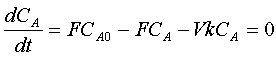
The steady-state model for the system is easily derived from a component material balance.
The steady-state model for the system is easily derived from a component material balance.
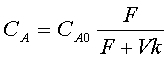
This can be rearranged to express the concentration as a function of the feed flow.
The steady-state gain is given by
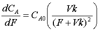
The gain always is positive. At low flow rates, the gain has its highest value, and as the flow increases (the control valve opens) the gain decreases in magnitude. Therefore, the proper installed valve characteristic would have a low gain at small valve openings and a large gain at large valve openings. This is generally the shape of an equal percentage characteristic. To finalize the design, we would have to substitute the numerical values for the parameters, and also, we would have to determine how much the supply pressure changes with valve opening.
Example 11) Low pressure drop valve:
The flue gas flow rate leaving a fired heater is adjusted to control the pressure in the fired heater. Select a valve for this application.
The flue gas flow rate leaving a fired heater is adjusted to control the pressure in the fired heater. Select a valve for this application.
Solution:
Generally, the volumetric flow rate of flue gas is high because of the large amount of nitrogen and the high temperature of the gas. Also, the fired heater is operated near atmospheric pressure. Therefore, a valve with a very low pressure drop is required. The standard choice is a butterfly valve, also called a stack damper. Note that a low pressure drop valve is also used when the cost of pumping or compression is very high.
Generally, the volumetric flow rate of flue gas is high because of the large amount of nitrogen and the high temperature of the gas. Also, the fired heater is operated near atmospheric pressure. Therefore, a valve with a very low pressure drop is required. The standard choice is a butterfly valve, also called a stack damper. Note that a low pressure drop valve is also used when the cost of pumping or compression is very high.
Example 12) Location of flow valve around a pump:
The liquid from the bottom accumulator of a distillation tower is pumped to a downstream unit. Decide where the flow control valve should be located.
The liquid from the bottom accumulator of a distillation tower is pumped to a downstream unit. Decide where the flow control valve should be located.
Solution:
The valve is required to provide a variable resistance for flow control. At least conceptually, the valve could be located before or after the pump. However, the liquid leaving the tower (or reboiler) is at its bubble point, so that any significant pressure drop in the valve located before the pump will lead to vaporization in the valve and partial vapor flow through the pump, leading to cavitation and damage. Therefore, the valve is located at the outlet of the pump, where the pressure is much higher and cavitation does not occur.
The valve is required to provide a variable resistance for flow control. At least conceptually, the valve could be located before or after the pump. However, the liquid leaving the tower (or reboiler) is at its bubble point, so that any significant pressure drop in the valve located before the pump will lead to vaporization in the valve and partial vapor flow through the pump, leading to cavitation and damage. Therefore, the valve is located at the outlet of the pump, where the pressure is much higher and cavitation does not occur.
No comments:
Post a Comment