where
- Active (Real or True) Power is measured in watts (W) and is the power drawn by the electrical resistance of a system doing useful work.
- Apparent Power is measured in volt-amperes (VA) and is the voltage on an AC system multiplied by all the current that flows in it. It is the vector sum of the active and the reactive power.
- Reactive Power is measured in volt-amperes reactive (VAR). Reactive Power is power stored in and discharged by inductive motors, transformers and solenoids
Power Factor
It is common to define the Power Factor - PF - as the cosine of the phase angle between voltage and current - or the "cosφ".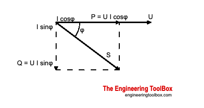
The power factor defined by IEEE and IEC is the ratio between the applied active (true) power - and the apparent power, and can in general be expressed as:
PF = P / S (1)A low power factor is the result of inductive loads such as transformers and electric motors. Unlike resistive loads creating heat by consuming kilowatts, inductive loads require a current flow to create magnetic fields to produce the desired work.
where
PF = power factor
P = active (true or real) power (Watts)
S = apparent power (VA, volts amps)
Power factor is an important measurement in electrical AC systems because
- an overall power factor less than 1 indicates that the electricity supplier need to provide more generating capacity than actually required
- the current waveform distortion that contributes to reduced power factor is caused by voltage waveform distortion and overheating in the neutral cables of three-phase systems
Example - Power Factor
A industrial plant draws 200 A at 400 V and the supply transformer and backup UPS is rated 200 A × 400 V = 80 kVA.If the power factor - PF - of the loads is only 0.7 - only
80 kVA × 0.7of real power is consumed by the system. If the power factor is close to 1 (purely resistive circuit) the supply system with transformers, cables, switchgear and UPS could be made considerably smaller.
= 56 kVA
Any power factor less than 1 means that the circuit's wiring has to carry more current than what would be necessary with zero reactance in the circuit to deliver the same amount of (true) power to the resistive load.
A low power factor is expensive and inefficient and some utility companies may charge additional fees when the power factor is less than 0.95. A low power factor will reduce the electrical system's distribution capacity by increasing the current flow and causing voltage drops.
Power Factor for a Three-Phase Motor
The total power required by an inductive device as a motor or similar consists of- Active (true or real) power (measured in kilowatts, kW)
- Reactive power - the nonworking power caused by the magnetizing current, required to operate the device (measured in kilovars, kVAR)
PF = P / [(3)1/2 U I] (2)
where
PF = power factor
P = power applied (W, watts)
U = voltage (V)
I = current (A, amps)
No comments:
Post a Comment